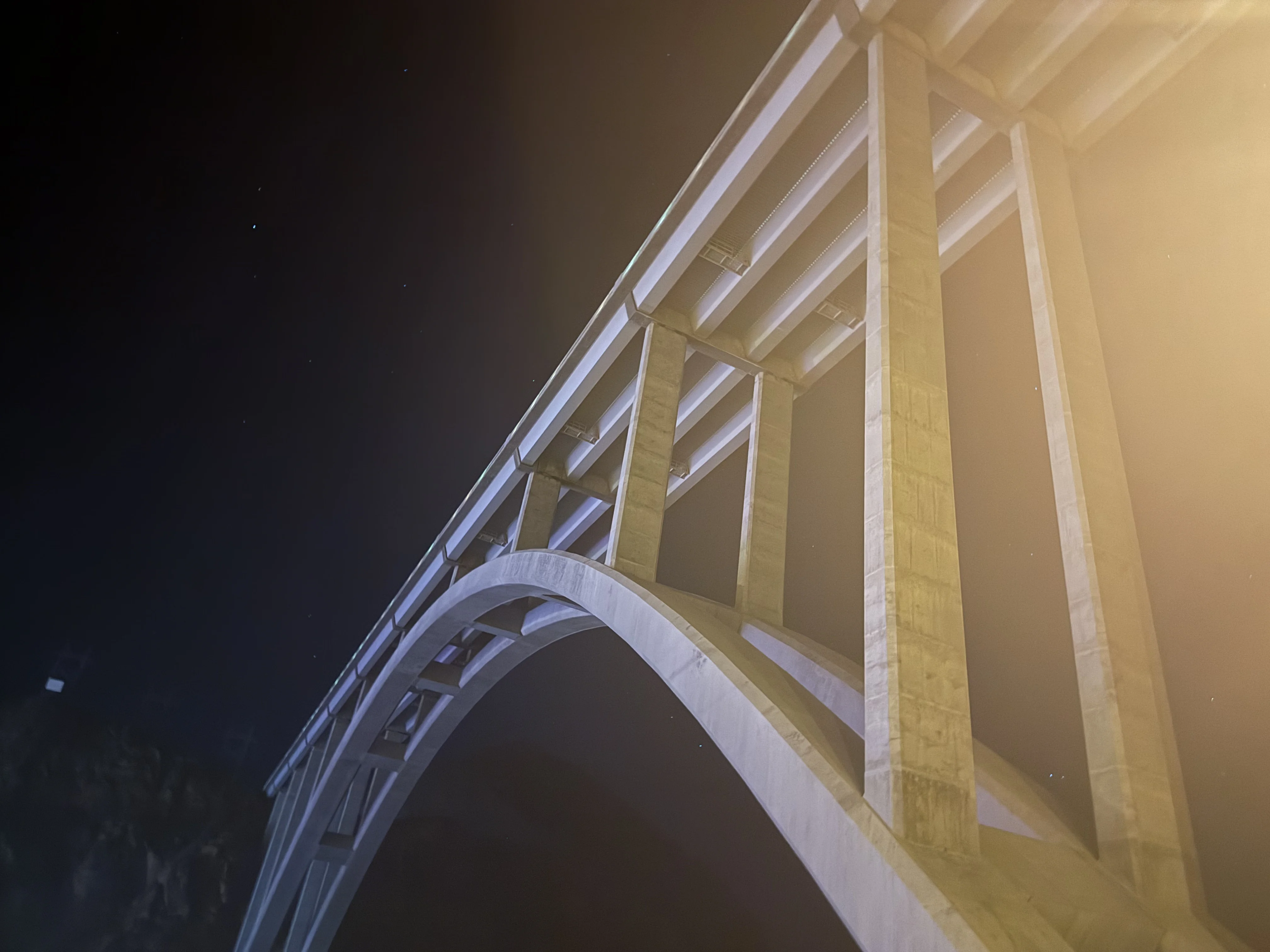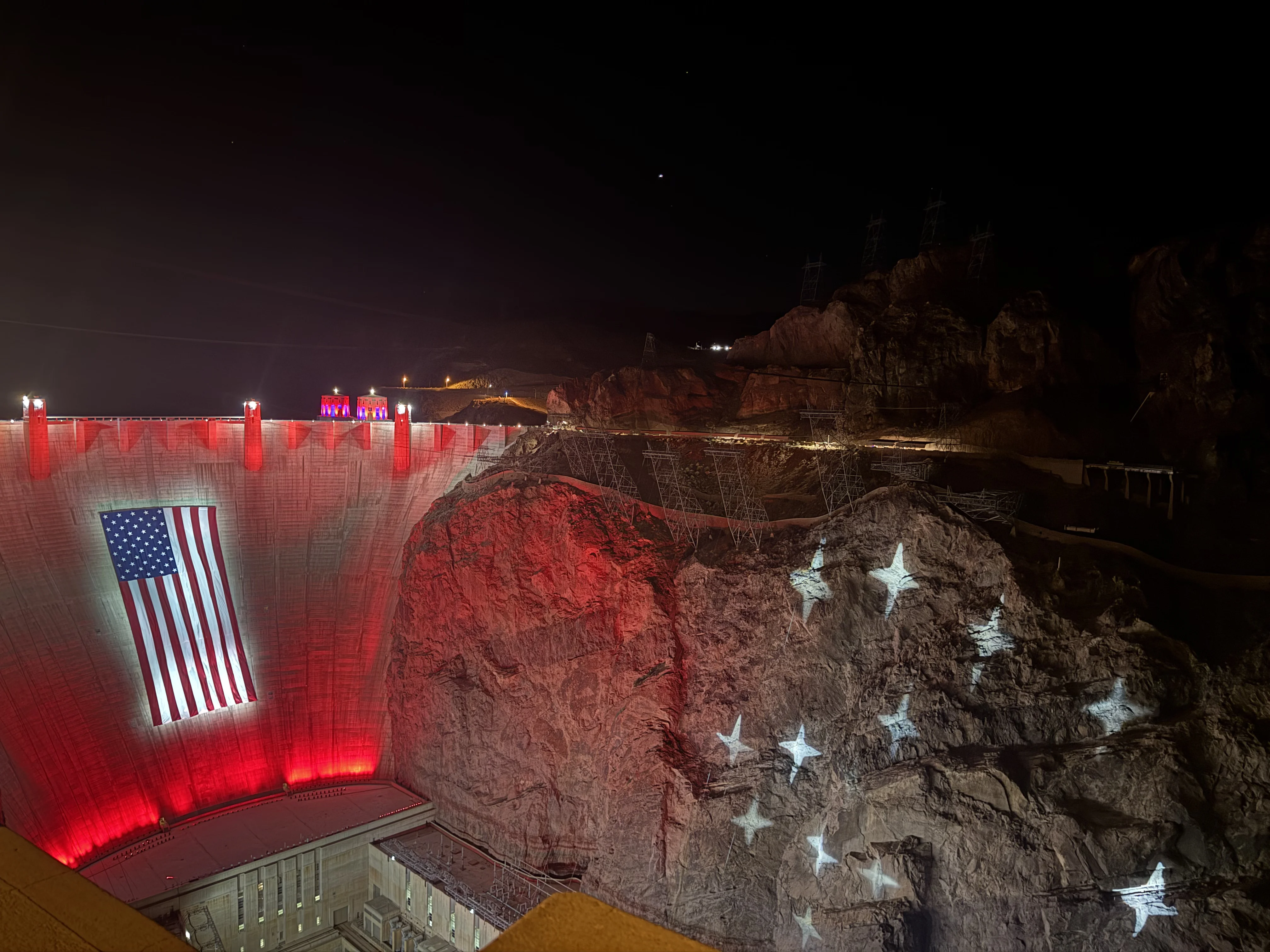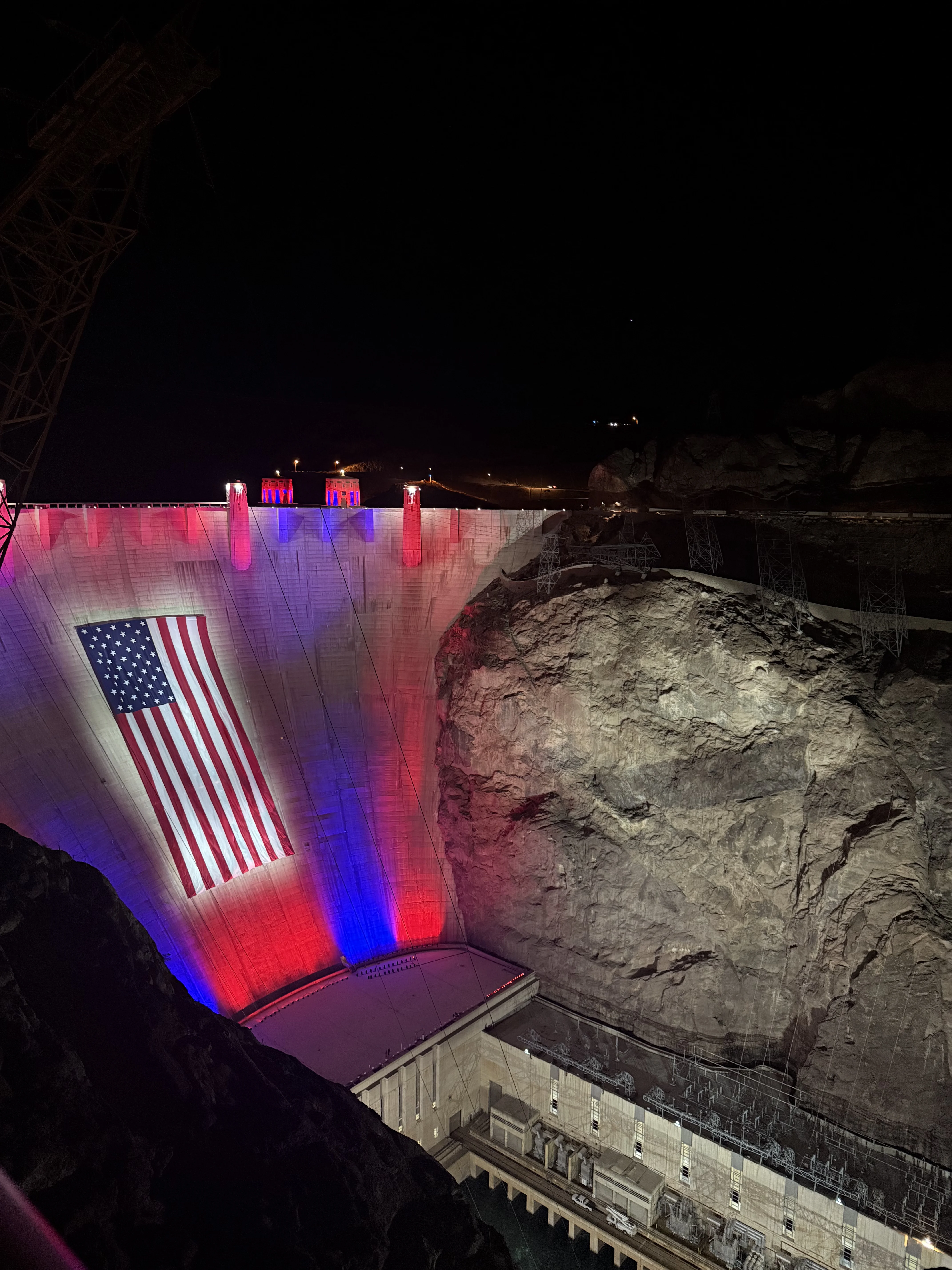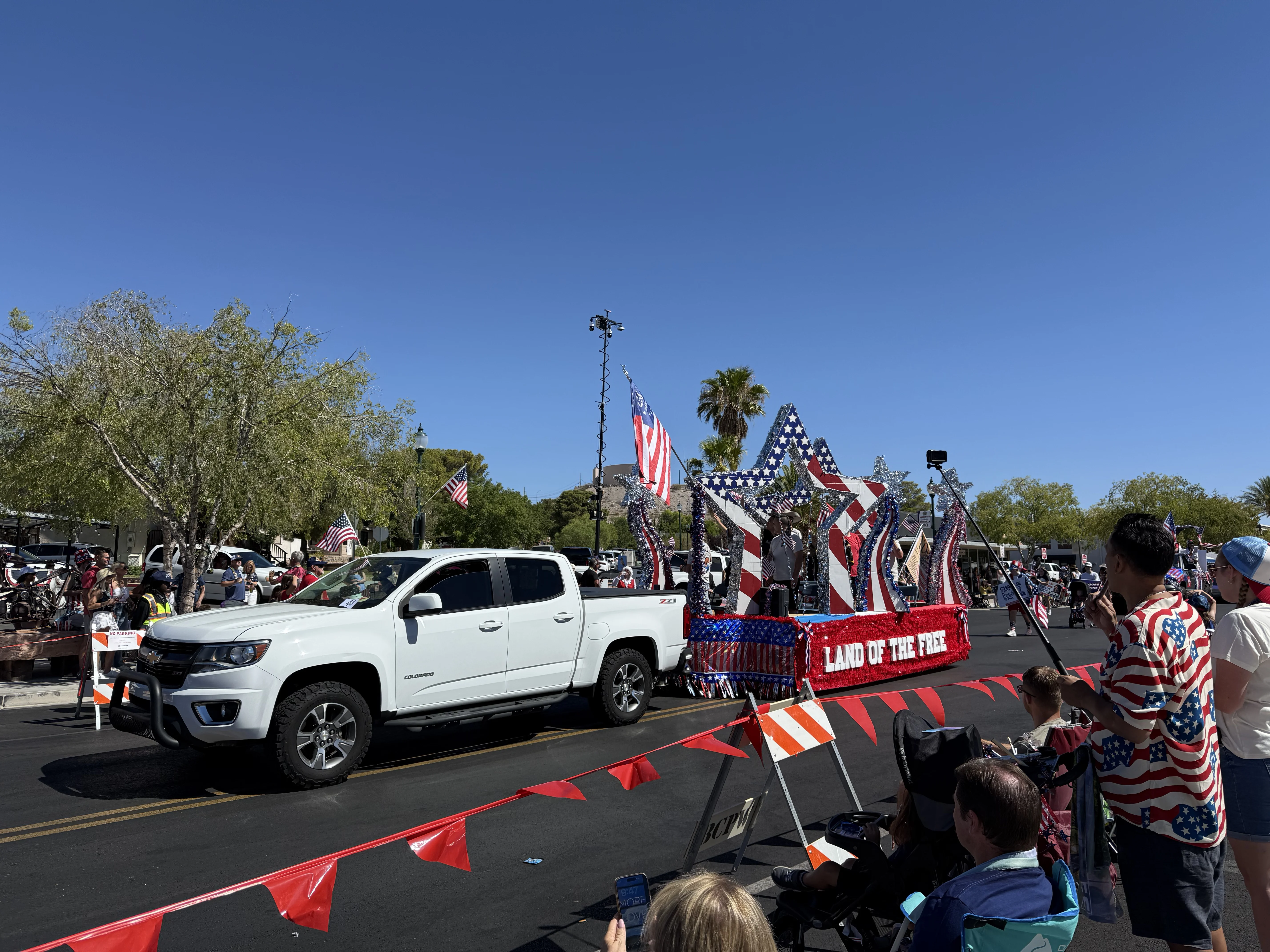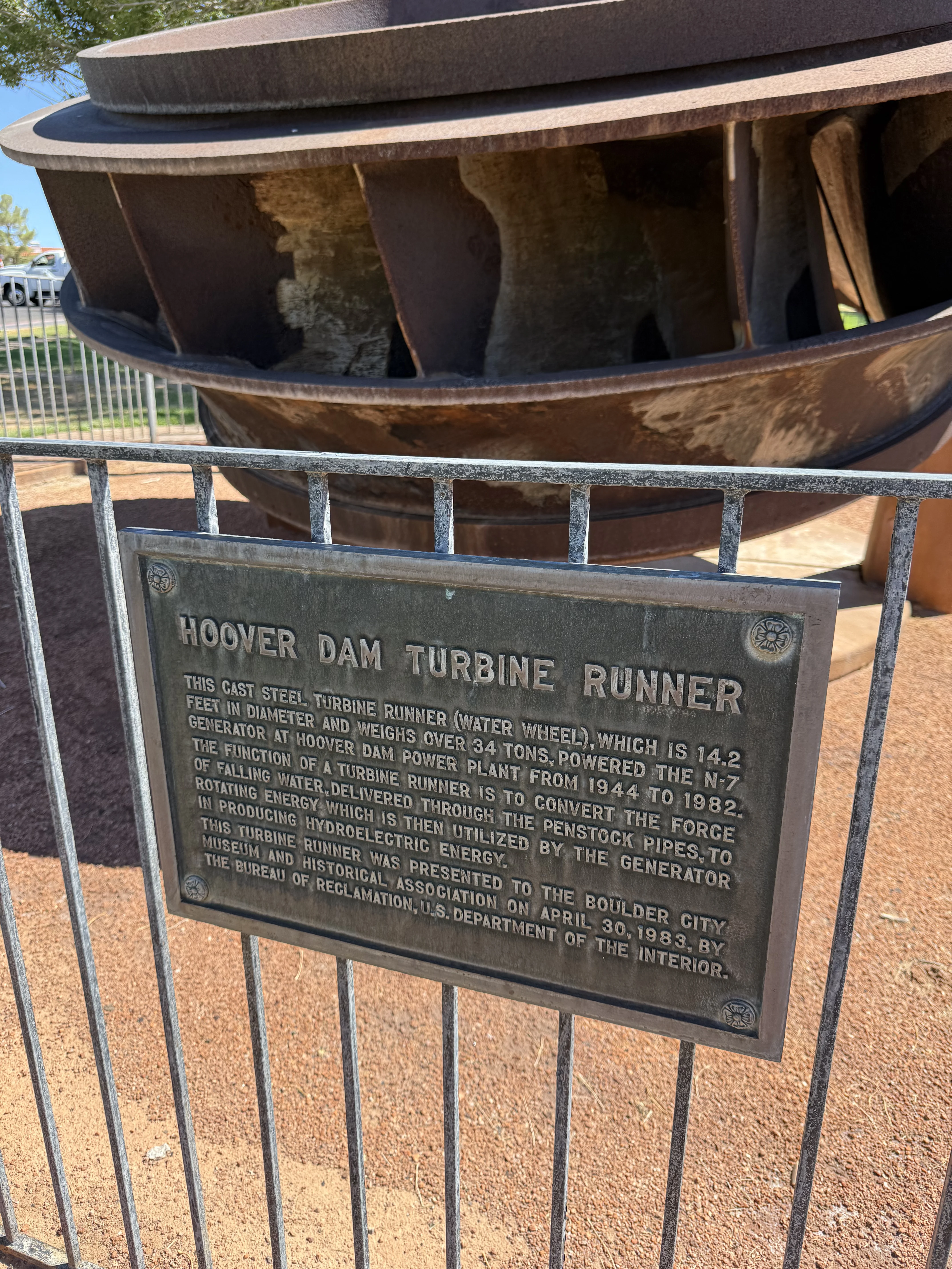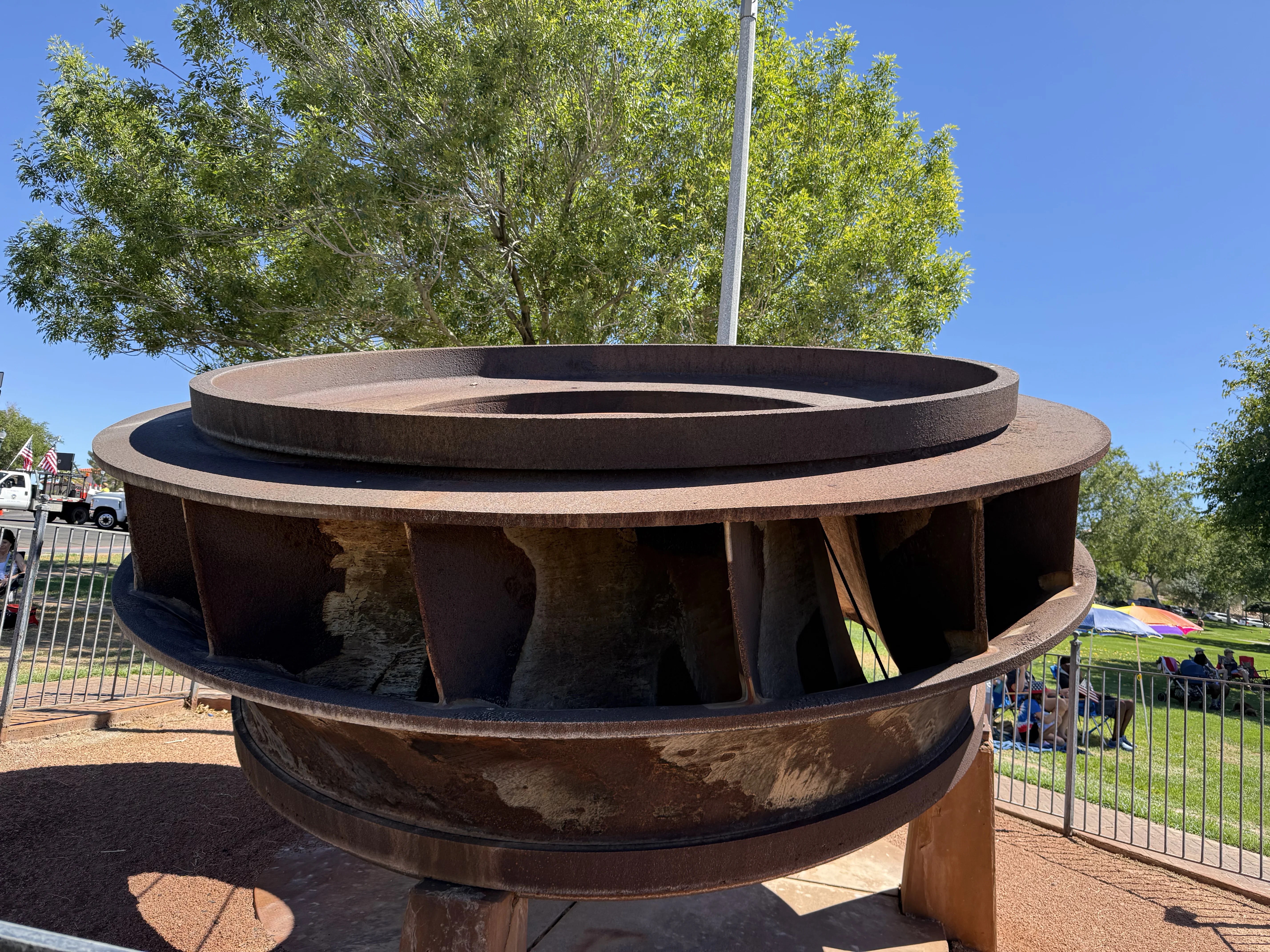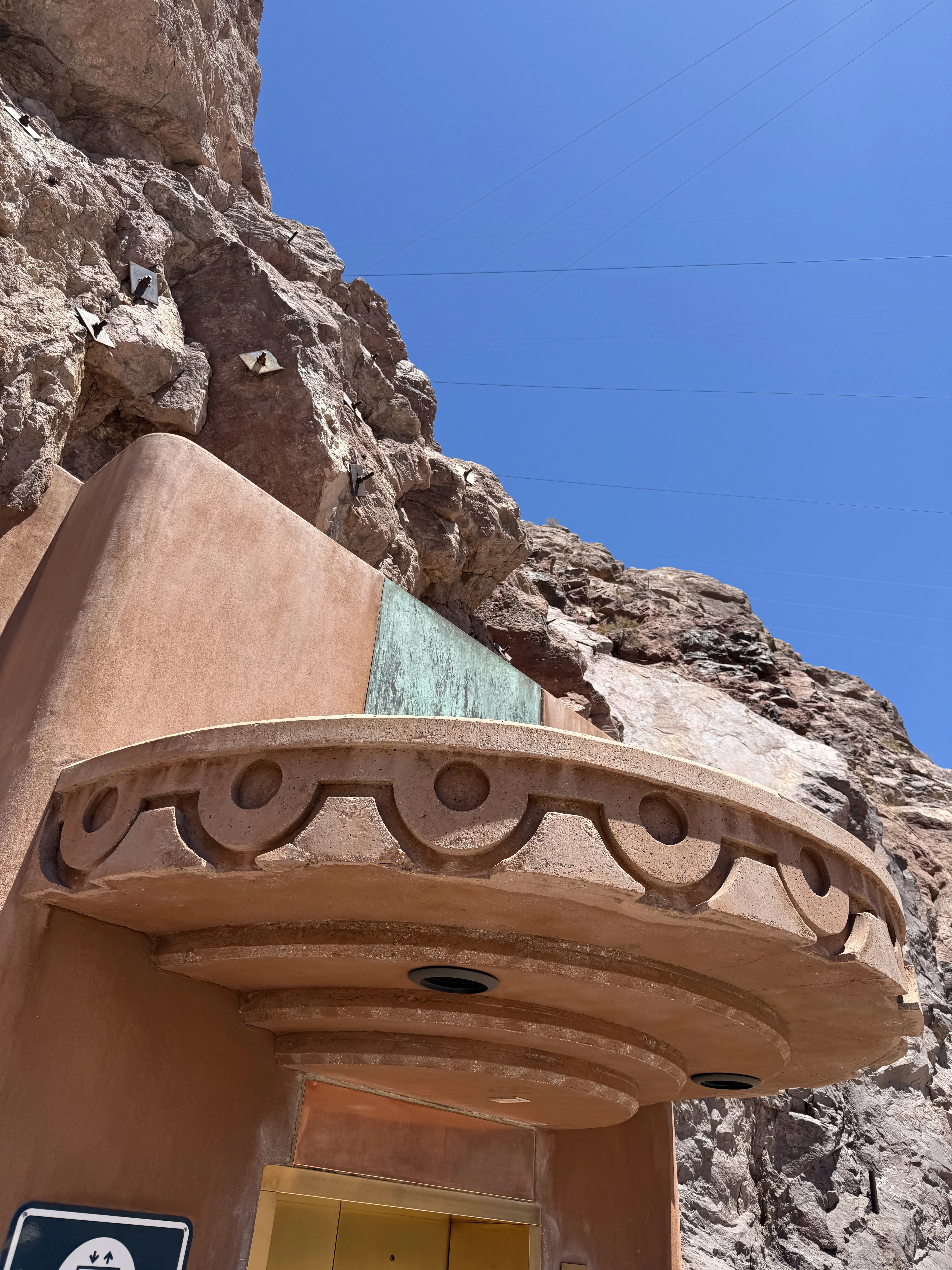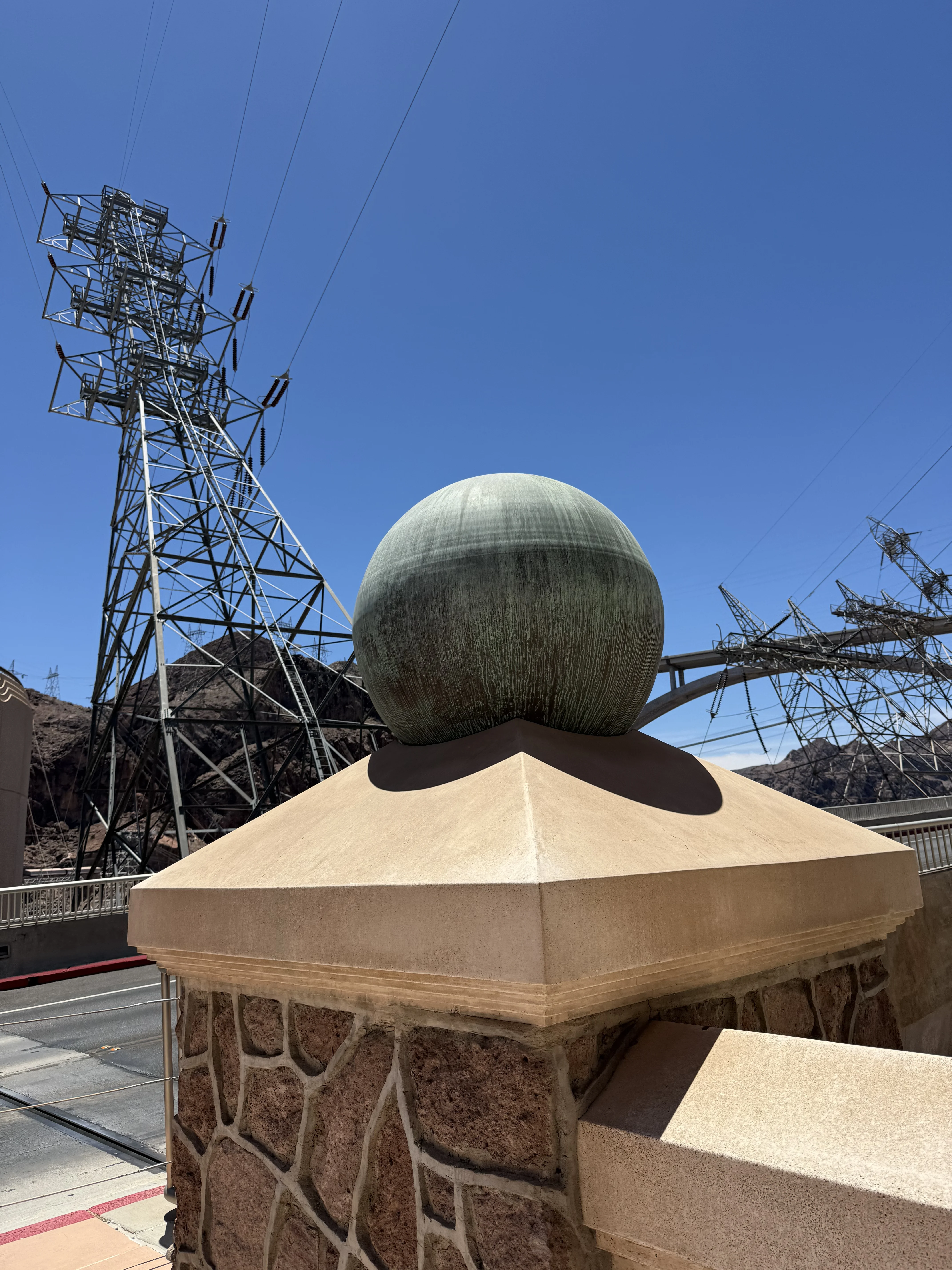
Hoover dam July 4th, 2026

Hoover Dam Historical Context

Context notes for nine construction-era photographs. Source: How Hoover Dam Was Built (LiveJournal copy of a historical photo essay). Captions combine the original article labels with a short description of what each photo shows.

Survey & site selection (pre-construction)

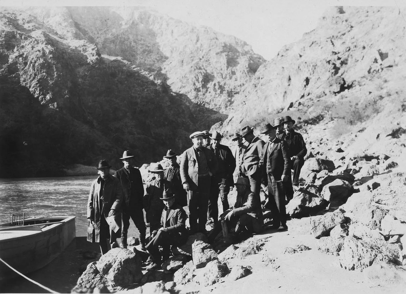
The 1925 survey party posed on the rocky bank of the Colorado River with a small boat at left
image_003 — The 1925 survey party

Original caption (1925): “The Party” about to embark for a trip through Boulder Canyon. They are assessing the potential sites for a dam on the Colorado River.

A group of men (engineers, surveyors, and officials) poses on the rocky bank of the Colorado with a small boat at left. This is early reconnaissance: before Black Canyon was fixed as the final site, parties floated the canyons to judge geology, river behavior, and possible dam locations. Boulder Canyon was the first favored site; construction later shifted to Black Canyon, though the federal project kept the name Boulder Canyon Project.
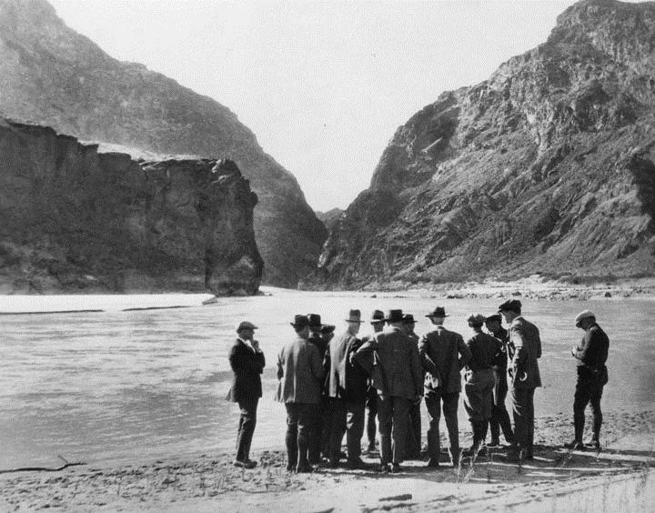
Engineers and politicians standing on a sandbar looking into Black Canyon, ca. 1928
image_004 — Engineers and politicians at Black Canyon

Original caption (ca. 1928): Engineers and politicians view dam site at Black Canyon.

About a dozen men in suits and hats stand on a sandbar at river level, looking into the narrow gap of Black Canyon. The Colorado still runs free between steep walls—the future dam axis. By the late 1920s the site debate had largely settled on Black Canyon (Nevada–Arizona border). The Colorado River Compact (1922, the “Hoover Compromise”) had already set how basin states would share water; federal authorization and funding still had to catch up (bill signed 1928; first construction money 1930).

Underground: diversion and spillway tunnels

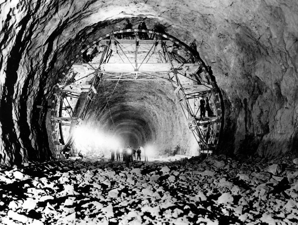
Workers and a large circular steel formwork inside a rough rock diversion tunnel
image_027 — Circular formwork in a diversion tunnel

Workers and a large circular steel form stand inside a rough rock tunnel. Four diversion tunnels (about 17 m / 56 ft diameter as excavated; ~15 m useful diameter after a ~0.9 m concrete lining) were driven through the canyon walls starting May 1931 so the river could be steered around the dam site. Total tunnel length was about 4.9 km. Forms like this shaped the concrete lining. After construction, tunnels were partly plugged with concrete and partly retained for penstocks and spillway discharge—so flood water does not go through the dam body itself, which improves stability.

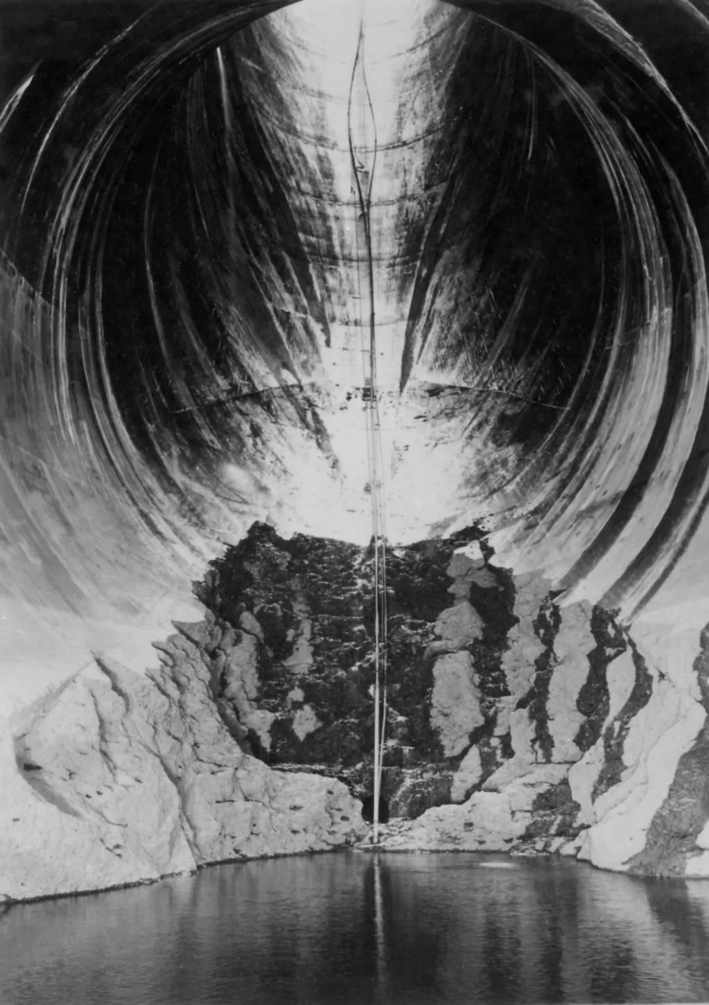
Looking up inside a finished concrete-lined diversion or spillway tunnel with residual rock and still water below
image_029 — Looking up a finished concrete tunnel

A dramatic upward view inside a huge concrete-lined bore: smooth curved walls, residual rock at the bottom, still water, and a thin cable hanging on axis. This is the kind of scale the diversion/spillway system reached (spillway tunnels were on the order of 50 ft diameter and thousands of feet long). The photo conveys why tunnel work was so dangerous—confined space, blasting, dust, and carbon monoxide—and why the finished tunnels feel almost cathedral-like.

Powerhouse and structure under construction

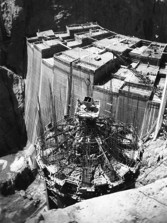
Looking down the dam face with powerhouse forms and an intake tower rebar cage under construction, ca. 1934
image_034 — Dam face, intake tower, and powerhouse forms

Related original caption (ca. 1934): Cement forms for the power plants / late-stage structural work on the dam.

Looking down along the dam: the curved concrete face fills the frame, crest decks show blocky formwork for the powerhouses, and in the foreground a tall cage of reinforcing steel outlines an intake tower under construction. A cableway bucket hangs over the work. Hoover Dam was poured as a stack of interlocking trapezoidal columns (not one solid monolith) so heat from curing concrete could escape; cooling pipes in the forms sped the process further. Intake towers later controlled how reservoir water entered the tunnels leading to the turbines.

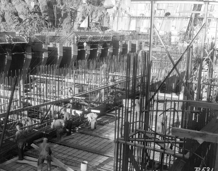
Laborers working among dense rebar cages and penstock openings at the power plant, ca. 1934
image_037 — Rebar and penstock openings at the power plant

Related original caption (ca. 1934): Closer look at power-plant construction; workers throughout.

Laborers work among dense rebar cages and timber forms at the base of the structure. Behind them, a row of large arched openings—penstock or draft-related portals—is framed in concrete. First concrete in the dam went in on June 6, 1933. Peak workforce was 5,251 (July 1934). Conditions were harsh; tunnel CO poisoning was a serious risk, and 96 people died over the life of the project. This was also among the first major U.S. jobs to make hard hats standard.
Machinery and water rising

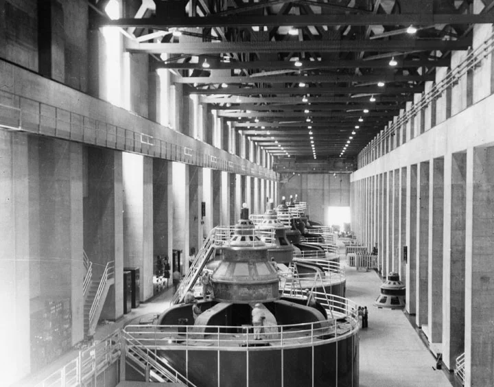
Upper generator room on the Nevada side of Hoover Dam with a row of massive generators, ca. 1936
image_039 — Generator room (Nevada side)

Original caption (ca. 1936): View of the upper generator room at Hoover Dam, on the Nevada side, where there are eight generators. (The Arizona side has nine.)

A long Art Deco–scale hall: massive cylindrical generator housings in a row, catwalks, hanging lamps, and workers dwarfed by the machines. Water from the intake towers and penstocks spins turbine runners below; generators turn that mechanical energy into electricity for the Southwest. The powerhouses sit at the dam’s base on both river banks.

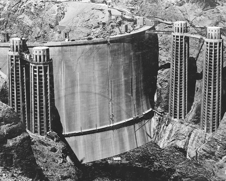
Upstream face of Hoover Dam with four intake towers as Lake Mead fills, ca. 1935
image_041 — Upstream face as Lake Mead fills

Original caption (ca. 1935): View of the intakes as the water level nears the top of Hoover Dam. / Upstream face slowly disappears as Lake Mead fills.

The finished arch-gravity face of the dam, with all four intake towers standing against the canyon walls (two Nevada, two Arizona). Debris and rising water collect at the toe of the upstream face. Once the diversion tunnels were sealed and the river was blocked, Lake Mead began to form—then (and for decades after) the largest reservoir in the United States by capacity. The roadway along the crest is already in place.

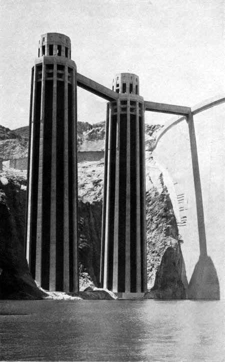
Pair of graceful intake towers standing in rising Lake Mead water, 1935
image_042 — Intake towers in the rising reservoir

Original caption (1935): View of the graceful intake towers whose gates control the release of the reservoir water. / From the Arizona spillway side toward the towers as water continues to rise.

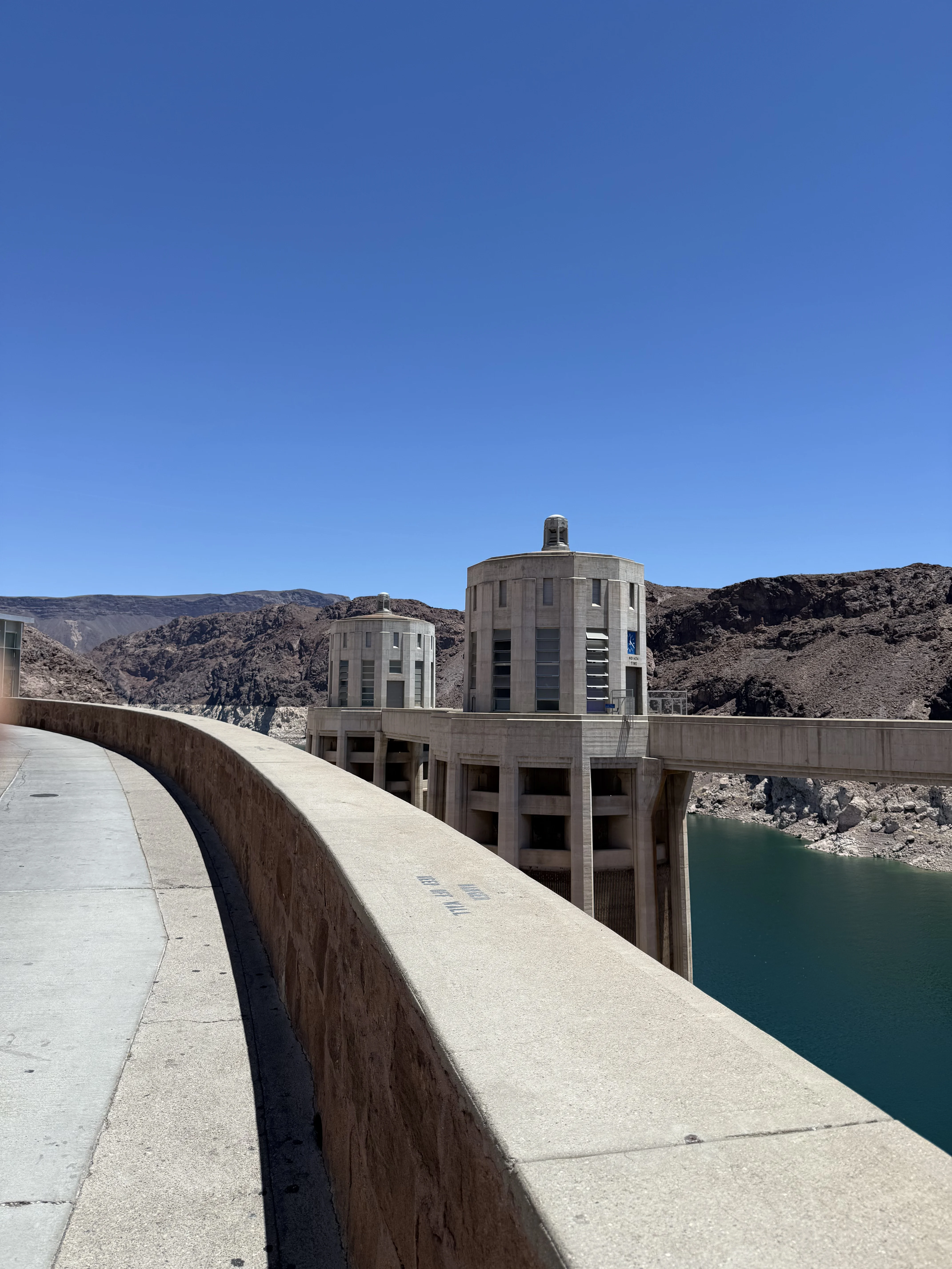
A close three-quarter view of a pair of intake towers standing in water, linked by an upper walkway; the dam crest and further structure fade into haze beyond. These towers are the “faucets” of the system: gates admit reservoir water into tunnels that feed the turbines (and related outlets). Their tall, fluted concrete form is one of the dam’s most recognizable design features.

Quick timeline

When What these photos touch
1925 Site survey party in the canyons (003)
~1928 Officials inspecting Black Canyon (004)
1931–33 Diversion tunnels drilled and lined (027, 029)
1933–35 Dam body, intakes, powerhouses poured (034, 037)
1935–36 Lake Mead rises; generators installed (039, 041, 042)